
Current Position:Home > Solutions >OEM Project >Petrochemical Industry
1. System overview
1.1 current status of equipment
1) The existing equipment system in the early 1990s, after more than ten years of operation equipment aging phenomenon is very serious, its control core PLC data is often lost, some automatic functions completely lost;
2) External detection components have not been calibrated for many years, and many components fail to detect, so it is difficult to accurately monitor the situation on the spot.
3) the original design is too complicated, with many detection points and redundant electrical control
4) due to aging, some functions of the control system fail and some completely lose their functions.
5), its equipment parts are basically eliminated, and once the parts are damaged, it is difficult to replace them, so it is difficult to maintain them.
6) The original system drawings and information are all in English, which brings great inconvenience to users and is not conducive to user maintenance and maintenance.
1.2 solution
Based on the above equipment, we consider replacing the original Schneider PLC with Siemens S7-300 series CPU and Uygur UN 300 series I/O, thus solving the above equipment problems.
Two, system requirements
2.1 hardware requirements:
1) replace the original "Schneider" PLC for SIEMENS S7-300 series PLC;
2) increase the EASYVIEW man-machine interface.
3) The original six instruments used for analog control and display were changed to UN300 A/D module control and displayed on man-machine and industrial computer.
4) Replacement of the original control cabinet, including low-voltage electrical appliances in the control cabinet, control system, PLC, control circuit, cabinet body, installation accessories, operation panel;
5), contactor and air switch are SIEMENS, button and indicator light are Schneider products.
6) maintain the hydraulic and pneumatic actuators of the system, including pressure and hydraulic valves.
7) the new control cabinet adopts the imitation map to make the cabinet, and the size of the cabinet remains unchanged.
8) Through the station control system of PROFIBUS standard fieldbus, the host computer is added to monitor the three units.
2.2 software requirements
1) realize the automatic function of the original unit through SIEMENS S7-300 programming software.
2) the human-machine interface has the following functions:
A) real-time data of unit operation.
B) and operation status of the unit;
C) and unit failure information;
D) and parameter setting of the unit.
E), unit control function.
3), Kingview:
A), state monitoring of the unit;
B) and process monitoring of the unit process.
C), engine compressor alarm stop point setting;
D), engine compressor fault stop point output
E), range setting;
F), implementing report output;
G), daily report;
H) and historical trend curve.
Three, system configuration and function realization
3.1 principle of equipment selection
1) equipment is selected by combining imported brand industrial control products with domestic brands.
2) domestic equipment is equipped with "3C" certified advanced, reliable industrial control products.
3) the control cabinet adopts the flame-proof structure with imitating structure.
3.2 main equipment and software
PLC: adopt S7-300 series PLC of SIEMENS company of Germany.
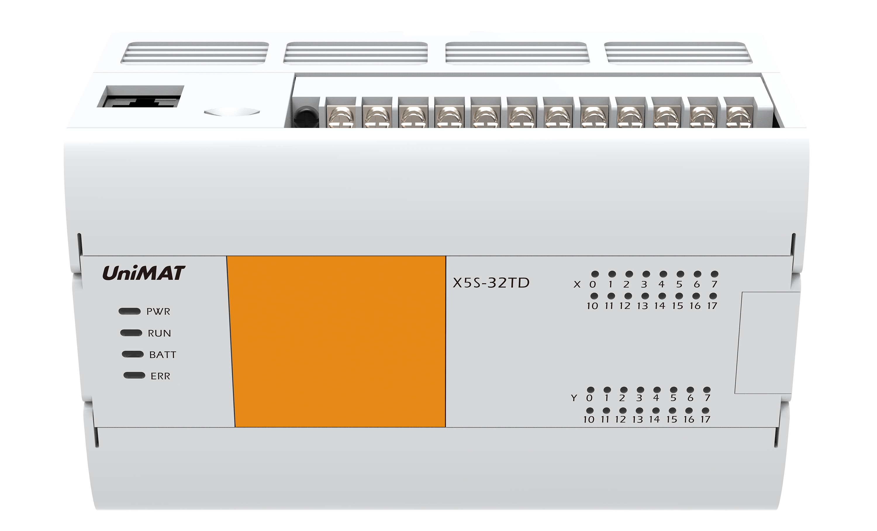
I/O: UN UNIMAT 300 series I/O;
Low voltage electrical appliances: basically use SIEMENS or Schneider Inc products;
Industrial control computer: Taiwan P4 industrial control computer.
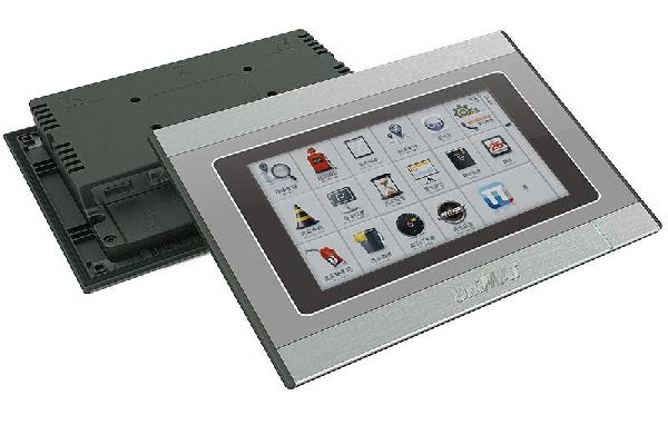
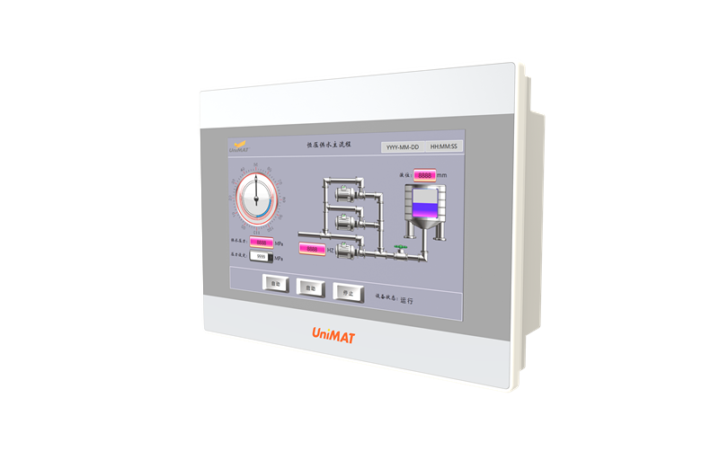
Touch screen human-machine interface: MT510T touch screen of eView company;
Bus and communication protocol: adopting Siemens PROFIBUS standard fieldbus, CP5611 PCI card and PROFIBUS-DP standard communication protocol;
Kingview: kingview 6.5 version of Beijing Asian control company.
SIEMENS STEP 7 V5.2+SP1.
Hardware implementation
1) System constitution: According to the user, the upper computer is used to centralize the monitoring of all units, and a central control system is composed of PROFIBUS fieldbus, as shown in the following:

System composition diagram
CPU315-2DP
I/O points: 1024 (max)
Storage capacity: 64KB
Processing speed: 0.3us/ step
MMC memory card, FLASH storage, data maintained for more than 10 years, and easy to replace, data will not be lost
The control core of the system, data processing and program operation, communication with man-machine, data exchange, with a DP port, good scalability
Analog input SM331
8 A/D conversion (3 standby)
The accuracy is 13 bits.
Analog input control, the original instrument control of the intake, outlet pressure and temperature digitization, through the PLC processing, can be on-site control and display on man-machine
SM321 digital input, SM322 digital output.
16, 24V, digital signal processing.
Human machine interface
10.4 ', 640*480, 256 colors.
Using Intel 32 bit processor.
Formula and real-time clock.
WINDOWS interface style
Display process parameters, historical data records, alarm records, process parameters can be modified.
* PC adapter
.MPI/RS232 conversion for PLC programming and man-machine communication
Industrial control computer
The IPC is Taiwan Advantech. The display is 21 inches of Philip.
PROFIBUS cable, PROFIBUS bus connector and CP5611 card.
3.2.2 software implementation:
Implementation of 3.4.1 configuration
The system interface is all Chinese.
It can dynamically monitor the current value of the process parameters of the compressor system and the working state of the technological process.
Can modify relevant parameters.
_can improve the self-diagnosis ability of the system, fault information is all processed in Chinese, and give warning display;
1) main screen:
All the analog parameters of the three units are monitored dynamically and real-time, so that the operator can master the operation status of all the units in the central control room.

Master picture
A) user login authority.
B) simultaneously displaying two engine, compressor operation parameters online.
C) record the engine running time.
D) record engine cumulative running time.
2), process gas flow monitoring screen:

Monitoring picture
A) dynamically display the operating parameters of the process gas on line.
B) has the animation display compressor unit technological process.
C) simultaneously displays the engine and compressor shutdown values, so that the operator can compare the operation data of the units.
3), engine compressor alarm stop point setting screen, the administrator passes this.
The picture can realize on-line modification of the alarm stop point, so as to achieve a variety of process requirements:

Alarm chart
A) the function of setting up the engine and compressor alarm stop point (with system permissions).
B) has the function of recording and displaying.
4) engine compressor failure stop point output screen:

Breakdown stop graph
A) the function of modifying the setting values of engine and compressor stop points (with system privileges).
B) has the function of recording and displaying.
C) alarm release and alarm muffler buttons.
D) engine emergency stop button
5) range setting screen:

Range setting picture
A) has a set of measuring ranges for engine, compressor detection points (temperature, pressure, speed)
B) has system permissions.
6) implementation of the report output screen:

Report output diagram
A) print the current engine and compressor operating parameters.
B) is written according to the user's actual report format.
7) daily table query screen

Report query graph
A) provides daily printouts for inquiries.
B) is compiled according to user's daily report format.
8) historical trend picture:

Historical trend map
Provide inquiring engine, compressor history trend curve and print out.
Through the Kingview, the operator can understand the operation status of the unit in the central control room.
The cause of the obstacle is to make the unit fault faster and more convenient.
3.2.2 human-machine realization
Through the MPI protocol and PLC communication, EasyBuilder 500 configuration software to set relevant parameters, and man-machine to achieve the following functions:
1) running state picture to monitor the running state of single machine.
2) the fault monitoring screen is used to display the fault of the unit.
3) Parameter setting screen to set and modify the parameters of the unit (with operating authority, only the administrator can operate).
Implementation of 3.2.3 network
Through the PROFIBUS-DP communication protocol, the S7-300 and Kingview are linked together to form a network, and the network is configured with Siemens STEP 7 V5.2+SP1 to realize a complete system. As a server, the industrial control computer is responsible for collecting data of all units, generating reports and historical curves, saving all data, and modifying the control and parameter settings of the units through PROFIBUS bus.
Four. Use effect analysis:
This system uses the mature and universal type of Siemens CPU and UNIMAT I / O module, good interchangeability, can reduce the number of spare parts, save costs. And make the whole system structure compact system circuit greatly simplified, high reliability, can greatly reduce the failure rate and maintenance costs. From the unified transportation to the present, the running state has been good.

 微博
微博