
Current Position:Home > Solutions >OEM Project >water treatment
1. introduction
In the water supply system, constant pressure water supply means that the outlet pressure remains unchanged when the water consumption changes in the water supply network. In this paper, computer (PC), programmable logic controller (PLC) and frequency converter are used to compose the frequency conversion constant pressure water supply monitoring system, which can realize constant pressure water supply and meet the requirements of energy saving and consumption reduction through frequency conversion and speed regulation, and is beneficial to realize the automation and remote monitoring of production. The change of water consumption is stochastic, and the water pressure is insufficient when the peak water is used. Frequency conversion constant pressure water supply system can automatically adjust the increase and decrease of pump, the running mode of pump motor and the speed of motor according to the pressure change of public pipe network by PLC and frequency converter to realize constant pressure water supply, which not only prevents energy consumption, but also avoids the impact of impulse current on equipment when motor starts.
2.working principle
Frequency conversion constant pressure water supply system uses a frequency converter to drive two high-power motors, which can operate in both frequency conversion and power frequency; a low-power motor, as an auxiliary pump motor.
Starting mode: In order to avoid the impulse current when starting, the motor uses frequency conversion starting mode, from the inverter output terminal to gradually increase the frequency and voltage. Before starting, the inverter must be reset.
Frequency conversion speed regulation: according to the water supply pipe network flow, pressure change automatic control inverter output frequency, so as to adjust the motor and pump speed, to achieve constant pressure water supply. If the output voltage and frequency of the equipment can not meet the requirements of water supply when the output voltage and frequency rise to the power frequency, the PLC issued instructions No. 1 pump automatically switched to the power frequency power operation, until No. 1 pump completely quit the frequency conversion operation, after resetting the inverter, No. 2 pump into frequency conversion operation.
Multi-pump switching: according to the need of constant voltage, adopt the principle of no primary and secondary switching, that is, "start first stop" access and exit. In the PLC program, by setting the working number of the frequency conversion pump and the number of power frequency pumps, the pump increase or decrease can be judged by whether the given frequency reaches the upper or lower limit frequency. When the water consumption is small, the auxiliary pump is used.
In order to prevent a pump from working for a long time, any pump can not run continuously for more than 3 hours. When the number of power frequency pumps is zero and one pump is running in the state of frequency conversion, start the timer, when it reaches 3 hours, the pump number of frequency conversion pump changes, that is, switch to another pump. When a pump runs in the power frequency state or the auxiliary pump starts, the timer stops counting and zeroing.
Fault handling: it can alarm the lower limit of water level, frequency converter, PLC fault and so on. PLC failure, the system automatically transferred to manual mode.
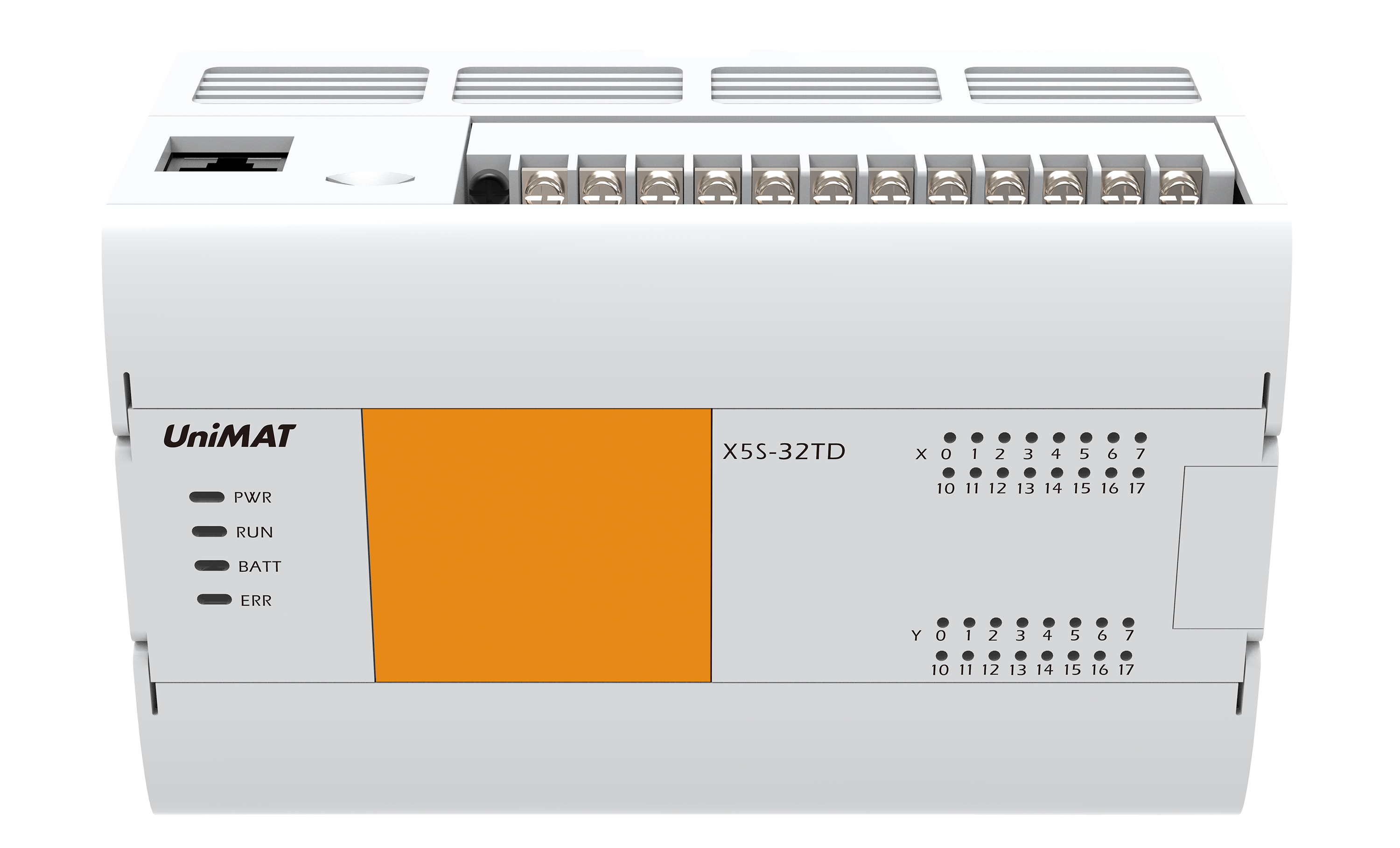
3.PLC control circuit
The system uses S7-200PLC as the slave computer. S7-200 PLC hardware system contains a certain number of input/output (I/O) points, but also can expand the I/O module and various functional modules, in order to ensure the stability of the system on the basis of reducing system costs, we choose UniMAT expansion module after the CPU. The input point is 6, and the upper and lower limit signals are I0.0 and I0.1 respectively. The output point is 10, and O0.0-O1.0 corresponds to the output terminal of PLC. The reset of the inverter is realized by the contact point of the output point O1.0 through an intermediate relay KA. According to the I / O point and address assignment of the control system, the system has five input points of switching quantity, nine output points of switching quantity, one input point of analog quantity and one output point of analog quantity. You can choose CPU224PLC (14DI/10DO) and expand a UniMAT analog module EM235 (4AI/1AO).
4.electronic control program design
Design and analysis of 4.1 pumping station software
(1) management of the working group quantity required by the "constant pressure" requirement.
In order to keep the water pressure constant, the output frequency of the frequency converter should be increased when the water pressure is lowered, and the second one should be started when one pump can not meet the constant pressure requirement. There is a criterion to determine whether a new pump needs to be started, that is, whether the output frequency of the inverter reaches the set frequency upper limit. This function can be achieved by comparing instructions. In order to judge the certainty that the frequency of frequency converter reaches the upper limit, the upper limit of frequency fluctuation caused by accidental factors should be filtered out, and time filtering should be considered in the program.
(2) management specification for pumping stations in pumping stations
Because the inverter pumping station hopes that every start motor is soft start, there is a rule that each pump must be used alternately, so the operation of many pumping station pumping set needs a management specification. In this design, the control requirement stipulates that any pump should not run continuously for more than 3 hours. Therefore, it is reasonable to use the new pump as frequency conversion when starting a new pump or switching the frequency conversion pump. In the specific operation, the converter is removed from the converter and connected to the power frequency power supply for operation, and the converter is reset and used for the start-up of the new pump. In addition, there is another problem of pump group management is the pump working cycle control, in this design, the use of pump number plus 1 method to achieve the frequency converter cycle control that is 3 plus 1 to 0 logic, the total number of power frequency pumps combined with pump number to achieve power frequency pump rotation.
4.2 the structure of the program and the realization of its program functions.
According to the foregoing, PLC has many functions in the constant pressure water supply system. Because the analog unit and PID adjustment need to compile initialization and interruption program, this program can be divided into three parts: main program, subroutine and interruption program.
(1) Some of the initialization of the system is done in the initialization subroutine, which saves scanning time. Use time

Initialization program
(2) the main program flowchart is shown in Figure 2. It has the most functions, such as the generation of the switch signal of the pump, the synthesis of the logic control signal of the contactor of the pump group and the alarm processing, etc. in the main program. The two constant values of life and fire dual constant pressure are directly programmed in digital way. The water supply system is set at 70% of the full scale, and the system is set to 90% of the full scale of the fire water supply system. The gain and time constants of the system are: gain Kc = 0.25, sampling time Ts = 0.2s, integral time Ti = 30min.

Master control program
(3) The interrupt program is shown in Figure 3. Its function is mainly used for the corresponding calculation of PID. It works under the function of PLC's normally closed relay SM0.0.

中断程序
5. concluding remarks
Constant pressure water supply technology uses frequency converter to change the frequency of the motor power supply, so as to adjust the pump speed to change the pump outlet pressure, than by regulating the valve to control the pump outlet pressure, with the effect of reducing pipe resistance greatly reduce the loss of interception. Because the variable displacement pump works in the frequency conversion condition, when its outlet flow is less than the rated flow rate, the pump speed reduces, reduces the bearing wear and heat, and prolongs the mechanical life of the pump and motor. To realize constant pressure automatic control, operators are not required to operate frequently, which reduces labor intensity and saves manpower.
The pump motor adopts soft start mode, accelerates according to the set acceleration time, avoids the impact of the current when the motor starts, and causes fluctuation of the grid voltage. At the same time, it avoids the surge of the pump system caused by the sudden acceleration of the motor.
Because the variable displacement pump works in the frequency conversion state, its speed is determined by the external water supply during its operation, so the system can save considerable electric energy in the operation process, and its economic benefit is very obvious. Because of this, the system can recover investment quickly, and the long-term benefits, its social benefits are enormous.
In practical application, the constant pressure water supply can be controlled by PLC, and the control program can be easily modified at any time to change the working time and working conditions of each component to meet different requirements. With relay or hardware.

 微博
微博