
Current Position:Home > Solutions >OEM Project > Hvac industry
1.Preface
This paper introduces in detail the HVAC control system scheme of 2x600MW supercritical unit in Tianji Power Plant of Huainan Coal-fired Power Base in Anhui Province. It also reveals the application of UniMAT PLC in the control system and provides a solution with higher cost performance for the industry.
2.System overview
The system of this power plant mainly includes the central chilled water system of the main workshop area, the hot water heating system of the central heating station in the factory area, the ventilation and air conditioning system of the steam turbine room, the ventilation and air conditioning system of the central control building, the ventilation and air conditioning system of the dust removal and electrostatic precipitation control building. Each system includes the functions of monitoring, programming and data processing. The whole system is set up in manual and automatic mode (switching between local control panel and LCD of centralized monitoring station).
3.System requirements
Ventilation and air conditioning system of central control building and central chilled water system of main workshop area; ventilation and air conditioning system of steam turbine room; hot water heating system of central heating station in factory area; ventilation and air conditioning system of dust removal and electrostatic precipitation control building are monitored by an independent PLC to ensure the safety of operation and maintenance.
The functions of the control system include:
Centralized monitoring of all monitoring points of the system can also be monitored locally.
All the controlled parameters can be set at the central control station and the local controllers.
With manual control function, the system can be controlled separately during commissioning, maintenance and operation.
It has configuration and programming functions, and has a password.
Display the parameters of each monitoring point, the status of each operating equipment and components, the dynamic graphics of each system and various historical data
It has the following sound and light alarm functions:
Operation equipment failure
The limit of monitoring points
After the equipment fails, it can be manually restarted on the control panel. When the system is running normally, it will be put into operation automatically.
Store the following historical information and display and print. The system has the function of power failure protection, and the standby power supply should meet the requirement of 72 hours continuous power supply.
Cumulative operating hours of running equipment (such as chillers, pumps, cooling towers and fans)
The time and place of equipment failure
Operation condition record within 10 hours before equipment failure
The interlocking time and location of equipment and components, such as interlocking with fire detection system, etc.
Linkage with automatic fire alarm system
When the host of the system fails, the subsystems should be able to work independently and all data, data and programs will not disappear.
4.System configuration and function realization
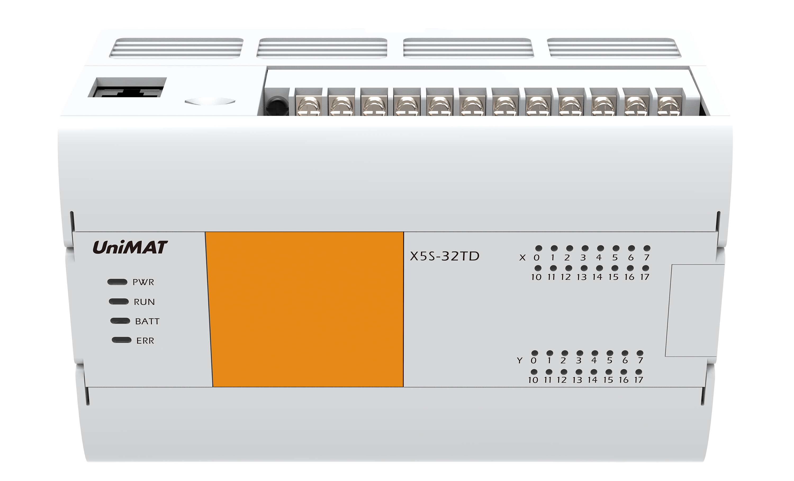
According to the system control requirements, the system is divided into centralized control building ventilation and air conditioning system, turbine room ventilation and air conditioning system, dust removal and electrostatic precipitation control building ventilation and air conditioning system, plant district central heating heating station hot water heating system, a total of four independent PLC systems, each system using Siemens (SIEMENS) PLC-300 series CPU + 100 million. The I/O module and accessories of dimension are made up of UN365 extended rack module. The WinCC user interface software and the industrial control unit are used to build the operation monitoring station of the system. As shown in the picture

1). centralized cooling water system in main workshop area
The central chilled water system in the main workshop area consists of air-cooled chillers and chilled water circulating pumps. The system is operated in summer. The system is as follows: air-cooled chillers, expanded constant pressure chillers, chilled water circulating pumps, electric switching valves at the inlet of chillers, electronic scale remover of chilled water system, and refrigeration. Water pressure differential bypass valve standby.
Interlocking and PID control: air-cooled water chiller and refrigerated water circulating pump have start-stop linkage control, air-cooled water chiller on-line group control, chilled water system and pressure difference by-pass control, for PID control loop, the chilled water system supply and return water main pipe set pressure difference by-pass valve, control system according to the supply and return water main pipe. Pressure automatically adjusts the water supply flow in the actual system. During the operation and shutdown of the system, the pressure of the system should be maintained in a set range by the expanding water supply and pressure fixing device (completed by the control system equipped with the expanding water supply and pressure fixing device). The expanding water supply and pressure fixing device will have a network signal interface with the automatic control system and output the pressure and fault signals to the automatic control system. Wait.
The automatic monitoring system only monitors the supply/return water temperature of the system, and has the following functions: when the supply water temperature of the system is lower than 5 degrees C (manually adjustable within the range of 0-10 degrees C), the monitoring system should alarm; when the return water temperature of the system is higher than 14 degrees C (within the range of 0-20 degrees C). When it is manually adjustable, the monitoring system should give an alarm; when the water pump is disconnected, the refrigerated water circulating pump should be equipped with a water flow switch or a water pressure differential switch protection device. When the pump is in a low flow state or low dropout, the water flow switch or water differential switch should be promptly reported to the police.
2). hot water heating system for central heating station in factory area
The hot water heating system of the central heating station includes heat exchangers and heating hot water circulating pumps.
The system runs in winter, specifically as follows: Expansion constant pressure unit, circulating water pump operation, heat exchanger imported electric control valve, heating system electronic descaling instrument operation, system pressure differential bypass valve standby.
The start of the system is manual, that is, the operator starts the program manually. The starting sequence should be as follows: starting the corresponding circulating water pump, electronic descaling instrument, delayed starting the corresponding heat exchanger inlet steam control valve.
The system's shutdown procedure is manual, which is initiated manually by the operator. The order of shutdown is opposite to the startup sequence.
The system should be set to start automatically according to the outdoor temperature. When the outdoor temperature is lower than 5 degrees C (the setting value should be adjustable: 0 ~ 15 degrees C), the system will start automatically.
The hot water circulating pump interlocks with the steam valve in front of the steam-water heat exchanger, and the steam valve is opened after the hot water circulating pump is started. Conversely, the hot water circulating pump shuts down the steam valve before shutting down to ensure that the steam temperature is not too high, to protect the steam-water heat exchanger coil.
The temperature control, protection and alarm of the water supply and return of the system: the heating hot water supply temperature of the system is 95 C, and the return water temperature is 70 C. The automatic control system monitors the supply/return water temperature of the system and controls the steam regulating valve in front of the heat exchanger by comparing the measuring point of the supply water temperature with the setting point (95 degree C). At the same time, the necessary protection and alarm functions are set up for water supply temperature and backwater temperature.
The monitoring system should alarm when the water supply temperature of the system is higher than 100 C (manually adjustable in the range of 70 110 C), and when the backwater temperature of the system is lower than 55 C (manually adjustable in the range of 30 70 C), the monitoring system should alarm.
Pressure differential by-pass valve is installed in the main water supply and return pipe of the heating water system in this project. The control system automatically adjusts the water supply flow in the actual system according to the pressure on the main water supply and return pipe. This is the PID regulating loop.
During the operation and shutdown of the system, the pressure of the system shall be maintained within a set range by the expanding water supply and pressure fixing device provided by the demander (completed by the control system equipped with the expanding water supply and pressure fixing device). The expanding water supply and pressure fixing device shall be equipped with a network signal interface with the automatic control system, and the pressure of the system shall be output to the automatic control system. Fault signal and so on.
Water pump interruption alarm: The hot water circulating pump of this system should be equipped with water flow switch or water pressure differential switch protection device. When the pump is in low flow state or low pressure difference, the water flow switch or water pressure difference switch should alarm in time.
3). ventilation and air conditioning system in unit control room of centralized control building
The ventilation and air conditioning system of central control building unit control room will include 20.20m floor HVAC equipment room, 13.70m floor centralized control room, shift room, SIS room, engineer room and so on.
Unit switching control: the two air handling units in the air conditioning system are reserved for each other, and the operation switching of the air handling unit is manual/automatic according to the number of operating hours of the unit. The operating hours reach the predetermined value of 720 hours (the operating hours should be manually adjustable between 0 and 1000 hours).
The start of the system is manual, that is, the operator starts the program manually. The starting sequence should be as follows: opening the electric switching baffle and the new exhaust regulating baffle at the inlet and outlet of the corresponding operating air treatment unit, starting the blower and the return blower of the corresponding unit after 120 seconds delay (the delay time can be adjusted manually in the range of 0-240 seconds).
The system's shutdown procedure is manual, which is initiated manually by the operator. The sequence of shutdown should be as follows: stop the operation of the return fan and the blower in the corresponding air treatment unit, delay 120 seconds (the delay time can be adjusted manually in the range of 0-240 seconds), close the electric switching baffle and the new exhaust baffle at the inlet and outlet of the air treatment unit.
The system is divided into three operating conditions, namely, summer operating conditions, winter operating conditions and transitional season ventilation conditions. Under various operating conditions, the state of the equipment and components of the system is as follows:
Summer operating conditions: the air supply fan and return fan in the air treatment unit put into operation, the air supply and return switching baffle, new exhaust regulating baffle open, exhaust baffle, fresh air baffle are in the minimum opening; heating coil outlet of the electric two-way valve closed, cooling coil outlet of the electric two-way valve, humidifier into waiting The machine state, its operation will be adjusted according to indoor temperature and relative humidity, indoor temperature and humidity to the central control room as the benchmark.
Transition season operating conditions: the air handling unit in the fan and return fan into operation, feed and return switching baffle open, exhaust baffle, new exhaust regulating baffle, fresh air baffle, humidifier (including humidifying pump and solenoid valve) into standby state, its operation will be adjusted according to indoor temperature and relative humidity; However, the electric two way valve at the outlet of the hot water coil pipe is closed.
Winter operating conditions: the air supply fan and return fan in the air treatment unit put into operation, the air supply and return switching baffle, new exhaust regulating baffle open, exhaust baffle, fresh air baffle are in the minimum opening; cooling coil outlet of the electric two-way valve closed, heating coil outlet of the electric two-way valve, humidifier into waiting The machine state, its operation will be adjusted according to indoor temperature and relative humidity, indoor temperature and humidity to the central control room as the benchmark.
Switching of operating conditions
There are two ways to switch the operating mode of the system, that is, manual switching and automatic switching.
When manually switching, the operator will manually switch on the control panel.
When switching automatically, the control system will switch according to the requirements of various operating conditions. Automatic switching will be based on the cumulative continuous time (at this time the set value should be adjustable in the range of 0-48 hours) outdoor temperature measurement signal and the set value (sub-summer operating conditions transition season operating conditions and transition season operating conditions in winter operating conditions two, the set value should be adjustable in the range of 0-30 degrees C) The operation condition of the system is determined.
System and indoor temperature and humidity control: The system temperature and humidity control will be based on the temperature and humidity of the central control room as a benchmark to control the indoor temperature and its precision set value refer to the indoor design parameter table. The temperature setting value is manually adjustable in the range of 10 C 35 C and the precision is manually adjustable in the range of 0.1 C 5 C. The temperature and humidity of the central control room are detected by two points, and the other rooms are detected by one point in each room to show the temperature and humidity of the room.
High and low limit alarm of indoor temperature and humidity in central control room: high limit temperature is 28 degrees C, low limit temperature is 18 degrees C, high limit relative humidity is 70%, low limit relative humidity is 30%;manually adjustable, precision in the range of 0.1 degrees C to 5 degrees C manually adjustable.
Indoor temperature control: according to the indoor temperature sensor (set a) detection value and indoor temperature setting value comparison, to adjust the opening of the electric two-way regulating valve, so that indoor temperature is maintained in a certain range.
Interlocking protection control with fire control system
When the fire control system sends out a fire signal (any room within the scope of the ventilation and air conditioning system) to the control panel of the system, the control system will stop the system operation, and feedback signal to the fire control center.
7). dedusting and electrostatic precipitator control building #1 furnace 380V electrostatic precipitator distribution room cooling ventilation system
System startup procedure and shutdown procedure
The start-up sequence of the system is manual. The starting sequence is as follows: opening the electric switching baffle at the inlet and outlet of the corresponding operating air treatment unit, starting the blower of the corresponding unit after 120 seconds delay (the delay time can be adjusted manually in the range of 0-240 seconds); the shutdown procedure of the system is manual, and the order of shutdown is: stopping the corresponding air. After 120 seconds delay (the delay time can be adjusted manually in the range of 0-240 seconds), the electric switching baffle and fresh air baffle at the inlet and outlet of the air handling unit are closed.
This cooling ventilation system is divided into summer operation and transition season.
The equipment and components of the system are as follows: the fan in the air handling unit is put into operation in summer; the air supply and return baffles are opened and the fresh air baffles are located at the minimum opening; the electric two-way valve at the outlet of the cooling coil enters the standby state, and its operation will be adjusted according to the indoor temperature and the relative humidity of the return air. The relevant system - the chilled water system is in operation and the exhaust fan is out of operation.
The equipment and components of the system are as follows: the blower in the air treatment unit is put into operation; the air supply baffle is opened, the return baffle is closed, and the fresh air baffle is maximum opened; the electric two-way regulating valve at the outlet of the cooling coil is closed; and the exhaust fan is operated.
Indoor temperature control: In this system, the set value of indoor temperature and its precision of 380V ESP distribution equipment of boiler # 1 is: 30 C 2 C in summer and excessive season; not controlled in winter. The temperature setting value is manually adjustable in the range of 10 C to 40 C, and the precision is manually adjustable in the range of 0.1 C to 5 C. Temperature control should be based on the indoor temperature sensor detected by the indoor temperature actual value and set value comparison, control the air treatment unit cooling coil outlet pipe electric two-way control valve opening, so that the air temperature to maintain within a certain range.
Indoor temperature alarm of switchgear room: high limit temperature is 35 degree C.
Low flow protection and alarm of blower in air handling unit: The blower in air handling unit of this system should be equipped with air flow switch or differential pressure switch protection device. When the blower or return fan is in low flow state or low pressure difference, the air flow switch or pressure difference switch should alarm in time.
Pressure differential protection and alarm of air filter in air treatment unit: Pressure differential switch protection device should be installed for the primary air filter in air treatment unit of this system. When the air filter air filter is larger than the differential pressure setting point, the differential switch should alarm in time.
Interlocking protection control with fire control system: When the fire control system sends out a fire signal (any room within the scope of the ventilation and air conditioning system) to the control panel of the system, the control system will stop the system operation and feedback signal to the fire control center.
8). dedusting and electrostatic precipitator control building #2 furnace 380V electrostatic precipitator distribution room cooling ventilation system
With the cooling and ventilation system of 380V ESP distribution equipment room of No. 1 boiler in the same ash removal and ESP control building, the corresponding KKS number was changed from 70SAU20 to 70SAU30 and 70QKU10 to 70QKU20.
9). air conditioning system in control room and ash removal main cabinet room
The air conditioning system of control room and ash removal main cabinet includes air handling unit and fan.
A. The starting sequence of the system is manual. The starting sequence is: opening the electric switching baffle at the inlet and outlet of the corresponding air handling unit, and starting the blower of the corresponding unit after the delay of 120 seconds (the delay time is manually adjustable in the range of 0-240 seconds). B. The shutdown procedure of the system is manual, and the order of shutdown is as follows: stop the operation of the blower in the corresponding air treatment unit, delay 120 seconds (the delay time can be adjusted manually in the range of 0-240 seconds), close the electric switching baffle and the fresh air baffle at the inlet and outlet of the air treatment unit.
The air conditioning system operates in summer and winter. Summer: the air supply fan in the air treatment unit put into operation; fresh air, supply air, return air baffle open; heating coil outlet electric two-way valve closed, cooling coil outlet electric two-way valve into standby state, its operation will be adjusted according to indoor temperature and return air relative humidity; related system - refrigerated water The system goes into operation. Winter: the air supply fan in the air treatment unit is put into operation; fresh air, supply air, return air baffle open; cooling coil outlet electric two-way valve closed, heating coil outlet electric two-way valve into standby state, its operation will be adjusted according to indoor temperature and return air relative humidity; related system - refrigerated water system The system is in operation.
Temperature and humidity control system will be based on the average temperature of each room as a benchmark to control the system indoor temperature and its precision set values are: summer can be set to 26 [C] [2] C; winter can be set to 18 [C] [2] C. The temperature setting value can be adjusted manually in the range of 0 C to 40 C, and the precision can be adjusted manually in the range of 0.1 C to 5 C. Indoor temperature detection: each room has 1 points.
Temperature control should be based on the indoor temperature sensor detected indoor temperature actual value and set value comparison, control the air treatment unit cooling coil / heating coil outlet pipe electric two-way control valve opening, so that the supply air temperature to maintain within a certain range.
Low flow protection and alarm of blower in air handling unit: The blower in air handling unit of this system should be equipped with air flow switch or differential pressure switch protection device. Air blower


 微博
微博